An empty bay,
mapped.
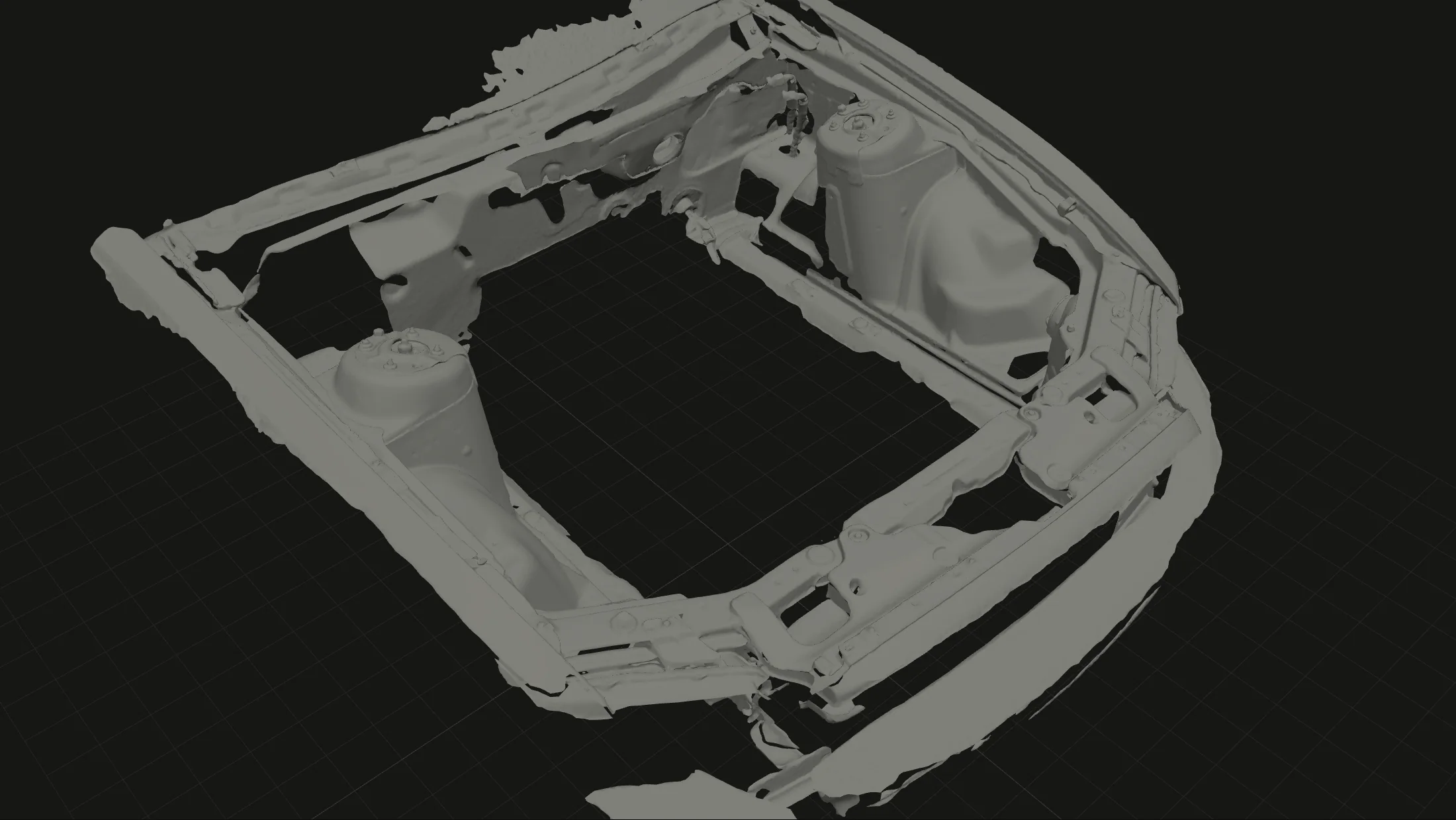
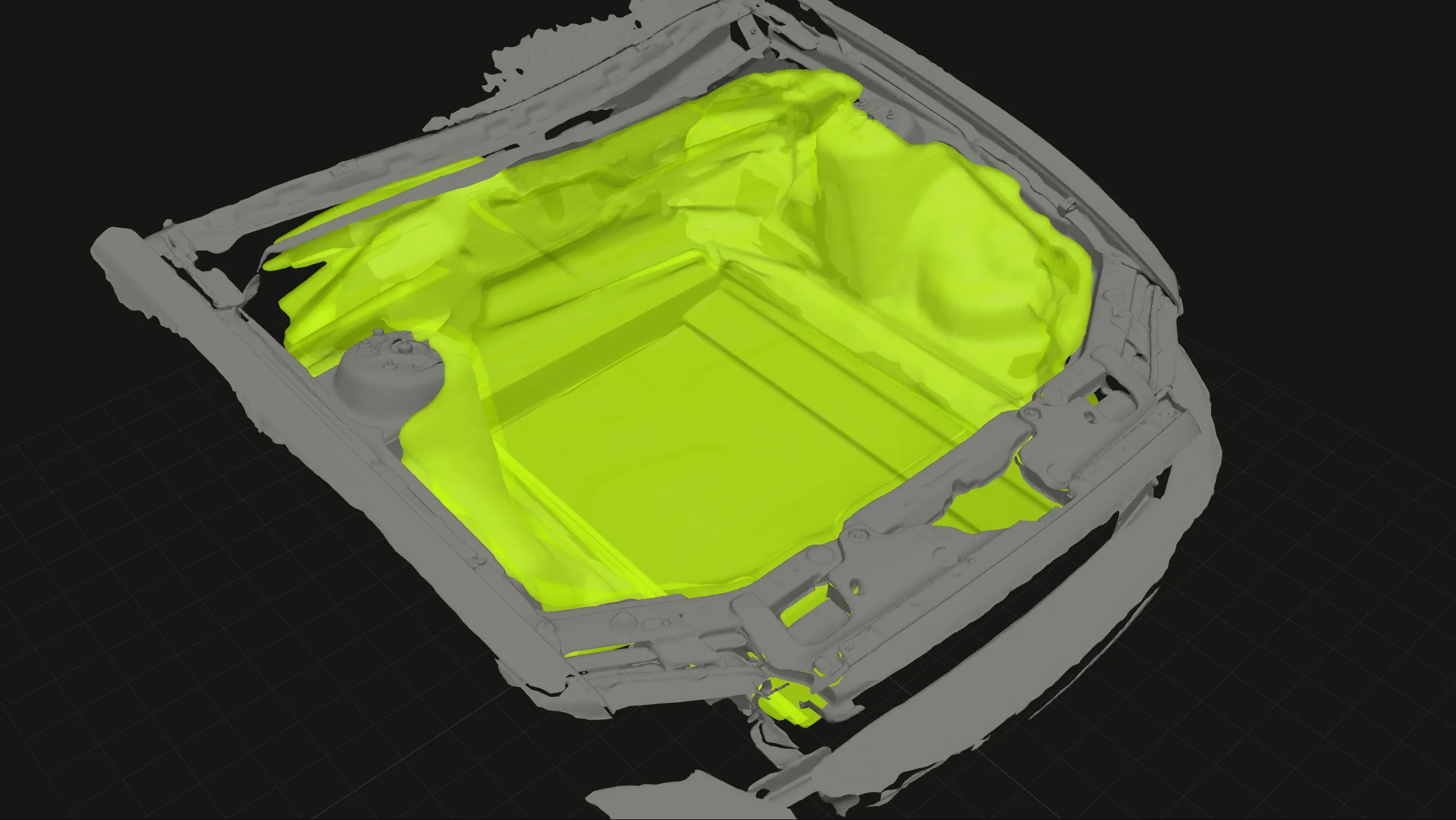
Engine out, nothing in its place yet. We scanned the stripped bay, set datums you can find again with a tape measure, put both hoods from case study 01 back on, and mapped the free space that's left to design into.
- Part
- stripped engine bay
- Input
- Einstar Vega · 2 scans · 7.1M triangles
- Output
- STEP · STL · hardpoint CSV
- Modeled by
- AI CAD agent + studio review
- Checks
- symmetry · registration · clearance
- Status
- Packaging reference · rev 2
 ScanFree space
re-measurable on the car
RMS, 165 points
≥10 mm off every surface
8 fixed before delivery
Look inside.
Drag to rotate · scroll to zoom · right-drag to panThe brief.
Same car as case study 01. The engine is out, and before anything new goes in, whether that's brackets, ducting, a cooling package or a whole drivetrain, the client needs to know what space is really there, and where it's measured from.
The job wasn't to rebuild the sheet metal. It was a packaging reference: datums and hardpoints you can find again on the car, a free-space envelope you can design straight into, and the hood back on top, because the hood is the lid on all of it.
- Part
- stripped engine bay
- Scans
- full bay + front-section pass
- Hoods
- both, from case study 01
- Toolchain
- Python · Open3D · OpenCascade
- Deliverable
- datums · hardpoints · envelope STEP
How we ran it.
Same loop · different questionScan
The whole bay at about 1 mm point spacing, plus a second pass over the front. They're merged where they agree, and the second pass fills in what the first missed.
Set datums
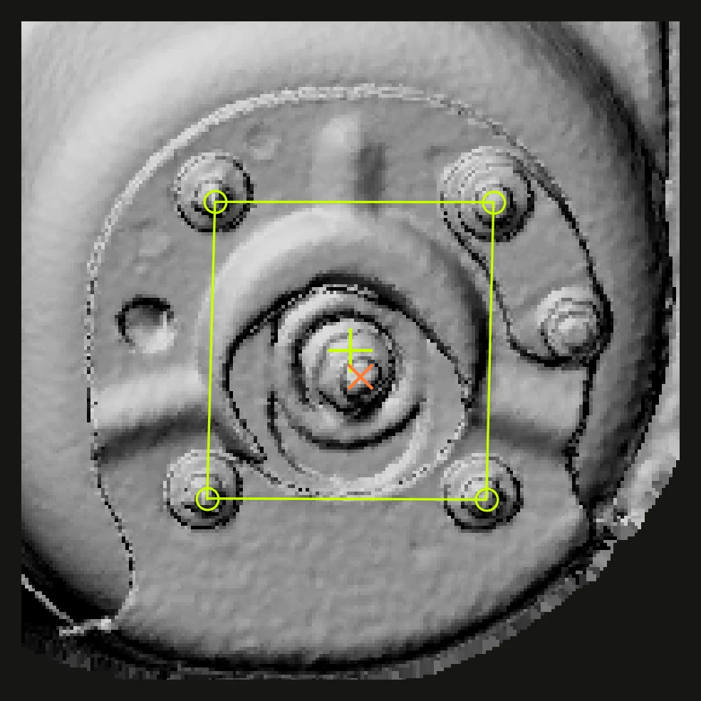
Centreline from the bay's own mirror plane. Height from the frame-rail tops. Fore-aft from the strut-mount bolt patterns, not the adjustable strut tops.
Find hardpoints
Stud patterns, rail walls, the core-support and firewall faces, and the latch pocket. Every number is tagged with where it came from and how far to trust it.
Map free space
Rays from the centreline and voxels at 5 mm, kept 10 mm off every scanned surface. Where the scan has holes, the walls are bridged and the bridged areas are mapped.
Put the hood back
Each hood's edge is fitted to the fender tops along both shut lines. The underside then becomes the envelope's lid.
Deliver
A STEP with labelled datums, hardpoints and envelope solids, slim meshes for CAD, the hoods placed in the bay frame, and a hardpoint CSV.
Datums you can find again.
Measured, then confirmed on the carA packaging reference is only useful if the person holding the tape measure lands on the same zero. So every datum is a physical feature, and every one was checked against something independent.
| Datum | Defined by | Check |
|---|---|---|
| Centreline | The bay's left/right mirror plane | mounts 0.7 mm off |
| Height zero | Both frame-rail tops, one plane | 1.45 mm RMS · level ✓ |
| Fore-aft zero | Centre of the two strut-mount stud patterns | sides agree to 1.0 mm |
| Handedness | Brake-booster pocket on the driver's side | LHD ✓ |
The strut top isn't the datum. These towers carry adjustable camber plates. The strut shafts sit 7.6 mm and 12.9 mm inboard of their mounts, and the two sides differ. Anything packaged off the shaft would inherit an alignment setting, so the datum is the stud pattern, which doesn't move.
✓ = confirmed by the owner. Key hardpoints are held to ±2 mm; the full table stays with the client.
The space that's left.
Envelope · conservative by design
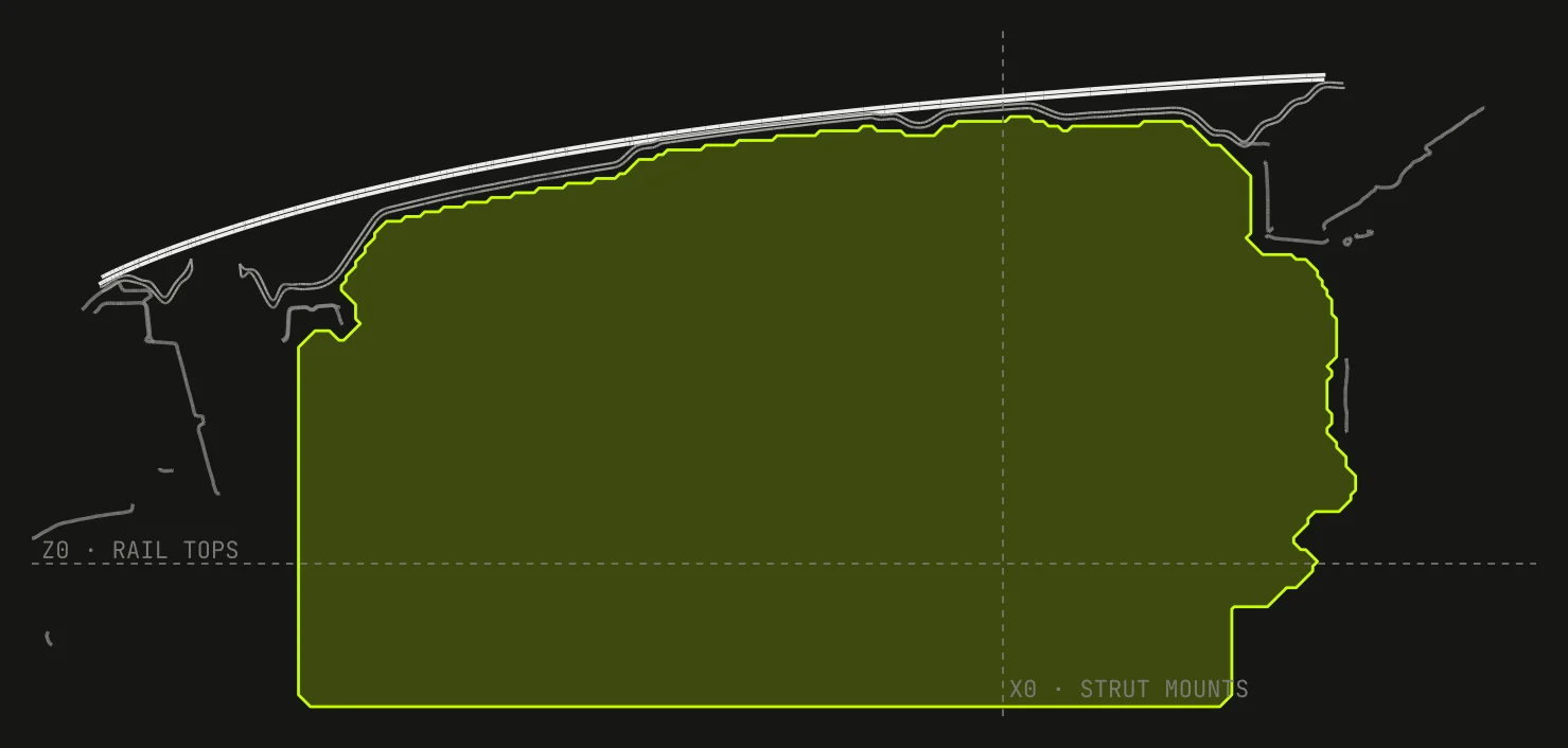
The envelope is the volume you can fill without touching anything that was scanned: rails, aprons, strut towers, core support, firewall, and the underside of the closed hood. It keeps 10 mm off every surface, and it errs small wherever the scan is unsure.
- Scan holes are bridged, never left open. About a quarter of the side walls are bridged, and those areas are mapped.
- A ray that escapes through a hole on one side is capped by the other side, because the bay is symmetric to a few millimetres.
- The front stops at the core support. A one-line switch opens the radiator opening too (+30 L).
- Each envelope is delivered as solid slices in the STEP, so CAD can check interference directly.
| Envelope | Volume L |
|---|---|
| Under hood B (stock shape) | 518 |
| Under hood A (dome + scoops) | 537 |
| Rev 1: assumed flat lid, before the hoods went on | 486 |
| Narrowest width between the towers | mm |
|---|---|
| At rail level | 755 |
| 100–200 mm above the rails | 865 |
Widths are envelope widths. The scanned walls are about 10 mm further out on each side.
Putting the hood back.
Registration · cross-checked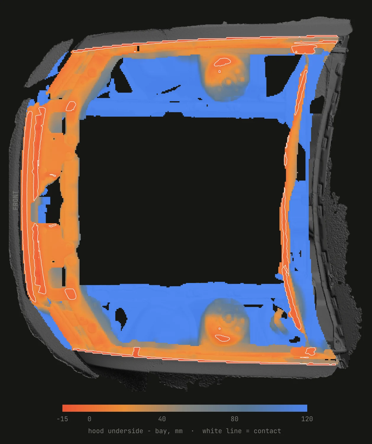
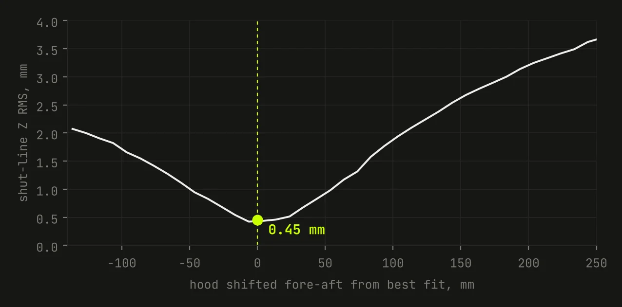
The hoods were scanned off the car, and the bay was scanned without a hood. What connects them is the shut line: a closed hood sits flush with the fenders along both sides. Fitting hood B's edge to the fender tops gives its height, pitch and fore-aft position.
| Check | Result |
|---|---|
| Shut-line fit, both sides | 0.45 mm RMS |
| Front half vs rear half, fitted separately | within 1.3 mm |
| Hood A, placed only through the shared crown | 0.48 mm median |
| Hood latch over the bay's latch pocket | ✓ |
The bay answered a question the hoods couldn't. Case study 01 flagged hood A's underside height as unmeasurable from its own scans. With the hood on the bay, the contact lines put it 16 mm higher, and the scan's skin depth with a 3 mm laminate says 15 mm. Two independent routes, 1 mm apart.
Still open.
- The hood is placed on the assumption that it sits flush with the fenders. A straightedge across each shut line would confirm it.
- As modeled, hood B's inner panel overlaps the bay by about 6 mm where it rests. Either its laminate is thinner than assumed or the seals compress. One caliper reading settles it.
- Nothing below the rails near the centreline was scanned (crossmember, steering rack), so the envelope's floor is an assumption for now.
- The two scan passes disagree by about 1 mm in places. Not yet resolved which is right.
Same rule as last time: what isn't finished gets published with the rest.
Delivered.
Every bound on the envelope is a named parameter: clearance, floor, lid, the radiator-opening switch. Change one and the whole thing rebuilds in about ten seconds.
Where AI-CAD broke.
Field notes · AI-CAD benchmarkSame agent, same rule: log every miss. A packaging job is less about modeling and more about deciding which evidence to trust, and that's where most of this run's misses were.
Tracehaus is a scanning and reverse-engineering studio. We're building toward being the physical ground truth for AI-CAD: real parts, real scans, and a grader that knows what a moldable, machinable part looks like. The public benchmark set will use parts we own.
on this part
+1 worked around
no error, wrong answer
3 parts so far
A good fit can sit at the wrong answer.
The first hood fit converged cleanly, 80 mm from the truth. Its scoring quietly rewarded staying on the data. A second, independent check caught it: the hood latch landed 90 mm behind the latch pocket.
Silent tools are the dangerous ones.
A standard mesh-slicing call returned almost nothing on a 5.6M-triangle scan, with no error. Only near-blank plots gave it away. Every tool's output now gets looked at before it's used.
The tallest feature isn't the datum.
The first strut-mount search grabbed the wrong surface, then the wrong studs. The fix was to look for the shape a designer would have used, a four-stud rectangle, rather than the highest or biggest thing.
Rays lie where scans have holes.
Rays went through apron gaps into the wheel wells, got shadowed by strut towers, and read the firewall edge-on as a side wall. Each fix is now a rule, and every bridged wall is mapped instead of hidden.
A shared reference beats more fitting.
Two separate scans of a hood can't give its thickness. Put both on the same car and the car becomes the shared surface: two independent estimates landed 1 mm apart.
| Score 1–5 | Acc. | Intent | Edit | Mfg. | Fit |
|---|---|---|---|---|---|
| Hood A | 3 | 4 | 3 | 4 | – |
| Hood B | 3 | 3 | 3 | 4 | – |
| Engine bay | 4 | 3 | 4 | n/a | – |
Agent self-scores. A packaging reference isn't manufactured, so it isn't scored on that. Fit is scored once parts designed against it are on the car.
| This part, by status | Count |
|---|---|
| Fixed | 8 |
| Worked around | 1 |
| Confirmed by the owner | 2 |
| Flagged | 2 |
| Still open | 2 |
Building AI-CAD? We bring the ground truth.
Physical parts and assemblies scanned with caliper-verified dimensions, CAD graded on accuracy, intent, editability, manufacturability and fit, and tagged failure data: the cases a "valid solid" test passes and a real car rejects.
Know the space before you fill it.
Send us the car, or the bay. We scan it, set datums you can measure from, and hand back the space that's actually there, with every assumption marked.
Client and vehicle details withheld. Images and figures are shared with permission.